Solid State
Mechanical Systems
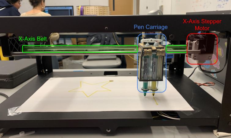
The mechanical system is composed of the gantry and the pen carriage.
The Pen Carriage
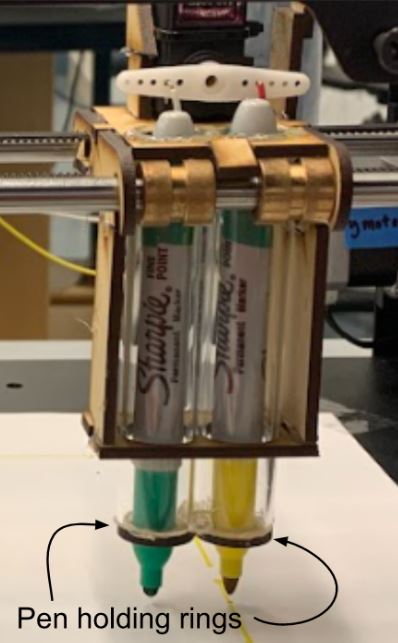
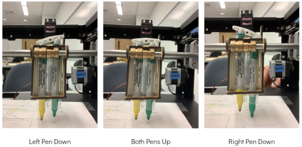
The pen carriage is designed to house 2 pens and a servo. When the servo turns one pen is lifted and the other is pressed to the paper. The pens are housed in clear tubes with small pen holding rings at the end of the tubes. The rings keep the pens from moving while the bot is drawing. The carriage was designed to slide on the bearings that were already on the gantry.
The Gantry
The gantry and body of the robot are made from a modified Makerbot Replicator 2X. Part of our goal was to make sure that our project was minimizing environmental impact by reducing waste. This Makerbot was broken and going to be disposed of, so we fixed it and used it instead. Most components of our bot are made of scrap or recycled materials. We challenged ourselves to not 3D print any components which led us to make some creative laser cut files for the pen carriage.

We modified the Makerbot gantry frame by cutting the sides down and drilling new screw holes for reassembly. We also removed the Z-axis stepper motor and build plate since we did not need them. The x-axis motor is connected to the x-axis belt. The pen carriage is attached to one side of the belt so that when the belt moves, the pen carriage with it.
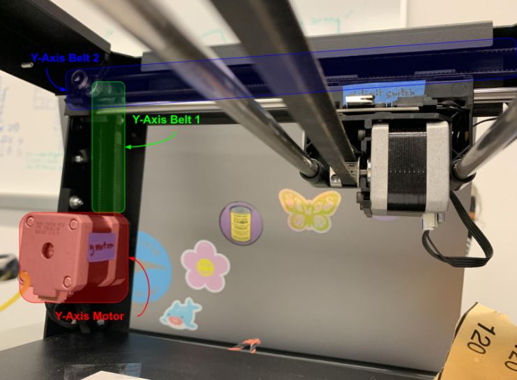
The y-axis motor is connected to the y-axis belt 1. Y-axis belt 1 spins the shaft that y-axis belt 2 is attached to. The x-axis assembly is on rails and connected to y-axis belt 2, so when belt 2 moves the x-axis assembly moves with it. This setup allows our gantry to draw continuous curves in any direction.